-

-
- (Page 12) Cellular Telephone Basics,
Appendix: Page 1 of Bell System Overview
-
- Learn the present by looking at the past. Here's some great
reading on the transition from mobile telephone service to cellular.
It outlines the IMTS system that influenced tone signaling in
AMPS, and gives some clear diagrams outlining AMPS' structure.
This is from the long out of print A History of Engineering
and Science in the Bell System: Communications Sciences (1925
-- 1980), prepared by members of the technical staff, AT&T
Bell Laboratories, c. 1984, p.518 et. seq.:
-
- 11.4.1 LAND MOBILE TELEPHONE SYSTEMS from
-
- A History of Engineering and Science in the Bell System:
Communications Sciences (1925 -- 1980)
Channel Availability
Mobile telephone service began in the late 1940s. By the seventies,
it included a total of thirty-three 2-way channels below 500
megahertz MHz), as shown in Table 11-2. The 35-MHz band, which
is not well suited to mobile service (because of propagation
anomalies), is not heavily used. The other bands are fully utilized
in the larger cities. In spite of this, the combination of few
available channels per city and large demand has led to excessive
blocking. The FCC's recent allocation of 666 channels at 850
MHz for use by cellular systems (described below) should change
this situation. This allocation is split equally between wire-line
and radio common carriers (each is allocated 333 channels). In
many areas, the wire-line carrier will be the local operating
company.
Use of conventional systems on the new channels would increase
the traffic-handling capacity by a factor of about 10. The cellular
approach, however, will increase the capacity by a factor of
100 or more. How this increase is achieved is discussed later
in this section. The potential for very efficient use of so valuable
and limited a resource as the frequency spectrum was a persuasive
factor in the FCC's decision.
Transmission Considerations
Radio propagation over smooth earth can be described by an inverse
power law; that is, the received signal varies as an inverse
power of the distance. Unlike fixed radio systems (for example,
broadcast television or the microwave systems described in Chapter
9), however, transmission to or from a moving user is subject
to large, unpredictable, sometimes rapid fluctuations of both
amplitude and phase caused by:
-
- Shadowing: This impairment is caused by hills, buildings,
dense forests, etc. It is reciprocal, affecting land-to-mobile
and mobile-to-land transmission alike, and changes only slowly
over tens of feet.
Multipath interference: Because the transmitted signal
may travel over multiple paths of differing loss and length,
the received signal in mobile communications varies rapidly in
both amplitude and phase as the multiple signals reinforce or
cancel one another.
Noise: Other vehicles, electric power transmission, industrial
processing, etc., create broadband noise that impairs the channel,
especially at 150 MHz and below.
Because of these effects, radio channels can be used reliably
to communicate at distances of only about 20 miles, and the same
channel (frequency) cannot be reused for another talking path
less than 75 miles away except by careful planning and design.
-
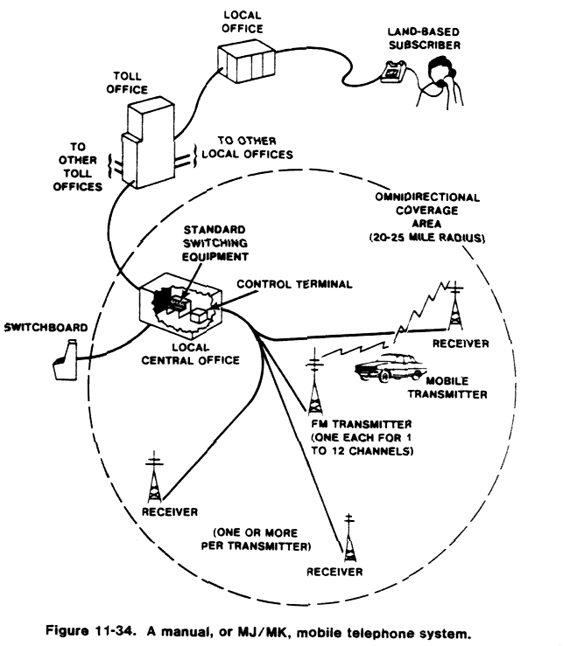
- In a typical land-based radio system at 15 or 450 MHz, one
channel comprises a single frequency-modulation (FM) transmitter
with 50- to 2;0-watt output power, plus one or more receivers
with 0.3- to 0.5 microvolt sensitivity. This equipment is coupled
be receiver selection and voice-processing circuitry into a control
terminal that connects one or more of these channels to the telephone
network (see Figure 11-34). The control terminal is housed in
a local switching office. The radio equipment is housed near
the mast and antenna, which are often on very tall buildings
or a nearby hilltop.
-

- Conventional System Operation
Originally, all mobile telephone systems operated manually, much
as most private radio systems do today. A few of these early
systems are still in use but because they are obsolete, they
will not be discussed here.
-
- More recent systems (the MJ system
at 150 KHz and the MK system at 450 KHz) [Improved Mobile Telephone
Service or IMTS, ed.] provide automatic dial operation. Control
equipment at the central office continually chooses an idle channel
(if there is one) among the locally equipped complement of channels
and marks it with an "idle" tone. All idle mobiles
scan these channels and lock onto the one marked with the idle
tone. All incoming and outgoing calls are then routed over this
channel. Signaling in both directions uses low-speed audio tone
pulses for user identification and for dialing. Compatibility
with manual mobile units is maintained in many areas served be
the automatic systems by providing mobile-service operators.
Conversely, MJ and MK mobile units can operate in manual areas
using manual procedures.
-
One desirable feature of a mobile telephone system is the ability
to roam; that is, subscribers must be able to call and be called
in cities other than their home areas. The numbering plan must
be compatible with the North American numbering plan. Further,
for land-originated calls, a routing plan must allow calls to
be forwarded to the current location. In the MJ system, operators
do this. Because of the availability of the MJ system to subscribers
requiring the roam feature, the MK system need not be arranged
for roaming.. .
-
(continues -->)

http://www.lucent.com .

|


