|
|
(Page 5) Cellular Telephone Basics continued . . .
VII AMPS Call Processing
Call processing diagram -- Keep track of the steps! Let's look at how cellular uses data channels and voice channels. Keep in mind the big picture while we discuss this. A call gets set up on a control channel and another channel actually carries the conversation. The whole process begins with registration. It's what happens when you first turn on a phone but before you punch in a number and hit the send button. It only takes a few hundred milliseconds. Registration lets the local system know that a phone is active, in a particular area, and that the mobile can now take incoming calls. What cell folks call pages. If the mobile is roaming outside its home area its home system gets notfied. Registration begins when you turn on your phone.
Registration -- Hello, World!
A mobile phone runs a self diagnostic when it's powered up. Once completed it acts like a scanning radio. Searching through its list of forward control channels, it picks one with the strongest signal, the nearest cell or sector usually providing that. Just to be sure, the mobile re-scans and camps on the strongest one. Not making a call but still on? The mobile re-scans every seven seconds or when signal strength drops before a pre-determined level. After selecting a channel the phone then identifies itself on the reverse control path. The mobile sends its phone number, its electronic serial number, and its home system ID. Among other things. The cell site relays this information to the mobile telecommunications switching office. The MTSO, in turn, communicates with different databases, switching centers and software programs.
The local system registers the phone if everything checks out. Mr. Mobile can now take incoming calls since the system is aware that it is in use. The mobile then monitors paging channels while it idles. It starts this scanning with the initial paging channel or IPCH. That's usually channel 333 for the non-wireline carrier and 334 for the wireline carrier. The mobile is programed with this information and 21 channels to scan when your carrier programs your phone's directory number, the MIN, or mobile identification number. Again, the paging channel or path is another word for the forward control channel. It carries data and is transmitted by the cell site. A mobile first responds to a page on the reverse control channel of the cell it is in. The MTSO then assigns yet another channel for the conversation. But I am getting ahead of myself. Let's finish registration.
Registration is an ongoing process. Moving from one service area to another causes registration to begin again. Just waiting ten or fifteen minutes does the same thing. It's an automatic activity of the system. It updates the status of the waiting phone to let the system know what's going on. The cell site can initiate registration on its own by sending a signal to the mobile. That forces the unit to transmit and identify itself. Registration also takes place just before you call. Again, the whole process takes only a few hundred milliseconds.
AMPS uses frequency shift keying to send data. Just like a modem. Data's sent in binary. 0's and 1's. 0's go on one frequency and 1's go on another. They alternate back and forth in rapid succession. Don't be confused by the mention of additional frequencies. Frequency shift keying uses the existing carrier wave. The data rides 8kHz above and below, say, 879.990 MHz. Read up on the earliest kinds of modems and FSK and you'll understand the way AMPS sends digital information. Data gets sent at 10 kbps or 10,000 bits per second from the cell site. That's fairly slow to begin with but fast enough to do the job. Since cellular uses radio waves to communicate, of course, signals are subject to the vagaries of the radio band. Things such as billboards, trucks, and underpasses, can deflect a cellular call. So the system repeats each part of each digital message five times. That slows things considerably. Add in the time for encoding and decoding the digital stream and the actual transfer rate can fall to as low as 1200 bps.
Remember, too, that an analog wave carries this digital information, just like most modems. It's not completely accurate, therefore, to call AMPS an analog system. AMPS is actually a hybrid system, combining both digital and analog signals. next page-->
Get a refresher below in the notes on digital: bits, frames, and slots
Notes
Bits, frames, slots, and channels: How They Relate To Cellular
- Here's a little bit on digital; perhaps enough to understand the accompanying Cellular Telephone Basics article. This writing is from my preliminary digital wireless series:
- Frames, slots, and channels organize digital information. They're key to understanding cellular and PCS systems. And discussing them gets really complicated. So let's back up, review, and then look at the earliest method for organizing digital information: Morse code.
- You may have seen in the rough draft of digital principles how information gets converted from sound waves to binary numbers or bits. It's done by pulse code modulation or some other scheme. This binary information or code is then sent by electricity or light wave, with electricity or light turned on and off to represent the code. 10101111, for example, is the binary number for 175. Turning on and off the signal source in the above sequence represents the code.
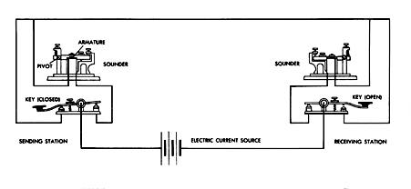
- Early digital wireless used a similar method with the telegraph. Instead of a binary code, though, they used Morse code. How did they do that? Landline telegraphs used a key to make or break an electrical circuit, a battery to produce power, a single line joining one telegraph station to another and an electromagnetic receiver or sounder that upon being turned on and off, produced a clicking noise.

- A telegraph key tap broke the circuit momentarily, transmitting a short pulse to a distant sounder, interpreted by an operator as a dot. A more lengthy break produced a dash.. To illustrate and compare, sending the number 175 in American Morse Code requires 11 pulses, three more than in binary code. Here's the drill: dot, dash, dash, dot; dash, dash, dot, dot; dash, dash, dash. Now that's complicated! But how do we get to wireless?
- Let's say you build a telegraph or buy one. You power it with, say, two six volt lantern batteries. Now run a line away from the unit -- any length of insulated wire will do. Strip a foot or two of insulation off. Put the exposed wire into the air. Tap the key. Congratulations. You've just sent a digital signal. (An inch or two.) The line acts as an antenna, radiating electrical energy. And instead of using a wire to connect to a distant receiver, you've used electromagnetic waves, silently passing energy and the information it carries across the atmosphere.
- Transmitting binary or digital information today is, of course, much more complicated and faster than sending Morse code. And you need a radio transmitter, not just a piece of wire, to get your signal up into the very high radio spectrum, not the low baseband frequency a signal sets up naturally when placed on a wire. .But transmission still involves sending code, represented by turning energy on and off, and radio waves to send it. And as American Morse code was a logical, cohesive plan to send signals, much more complicated and useful arrangements have been devised.
We know that 1s and 0s make up binary messages. An almost unending stream of them, millions of them really, parade back and forth between mobiles and base stations. Keeping that information flowing without interruption or error means keeping that data organized. Engineers build elaborate data structures to do that, digital formats to house those 1s and 0s. As I've said before, these digital formats are key to understanding cellular radio, including PCS systems. And understanding digital formats means understanding bits, frames, slots, and channels. Bits get put into frames. Frames hold slots which in turn hold channels. All these elements act together. To be disgustingly repetitive and obvious, here's the list again:
Frames
Slots
Channels
Bits
We have a railroad made not of steel but bits. The data stream is managed and built out of bits. Frames and slots and channels are all made out of bits, just assembled in different ways. Frames are like railroad cars, they carry and hold the slots which contains the channels which carry and manage the bits. Huh? Read further, and bear with the raillroad analogy.
A frame is an all inclusive data package. A sequence of bits makes up a frame. Bit stands for binary digit, 0s and 1s that represent electrical impulses. (Go back to the previous discussion if this seems unclear.) A frame can be long or short, depending on the complexity of its task and the amount of information it carries. In cellular working the frame length is precisely set, in the case of digital cellular, where we have time division multiplexing, every frame is 40 milliseconds long. That's like railroad boxcars of all the same length. Many people confuse frames with packets because they do similiar things and have a similiar structure. Without defining packets, let just say that frames can carry packets, but packets cannot carry frames. Got it? For now?
A frame carries conversation or data in slots as well as information about the frame itself. More specifically, a frame contains three things. The first is control information, such as a frame's length, its destination, and its origin. The second is the information the frame carries, namely time slots. Think of those slots as freight. These slots, in turn, carry a sliced up part of a multiplexed conversation. The third part of a frame is an error checking routine, known as "error detection and correction bits." These help keep the data stream's integrity, making sure that all the frames or digital boxcars keep in order.
The slots themselves hold individual call information within the frame, that is, the multiplexed pieces of each conversation as well as signaling and control data. Slots hold the bits that make up the call. frequency for a predetermined amount of time in an assigned time slot. Certain bits within the slots perform error correction, making sure sure that what you send is what is received. Same way with data sent in frames on telephone land lines. When you request $20.00 from your automatic teller machine, the built in error checking insures that $2000.00 is not sent instead. Most TDMA based systems use two slots out of a possible six. Now let's refer to specific time slots. Slots so designated are called channels, ones that do certain jobs.
Channels handle the call processing, the actual mechanics of a call. Don't confuse these data channels with radio channels. A pair of radio frequencies makes up a channel in IS-54 or digital cellular, and AMPS. One frequency to transmit and one to receive. In digital working, however, we call a channel a dedicated time slot within a data or bit stream. A channel sends particular messages. Things like pages, for when a mobile is called, or origination requests, when a mobile is first turned on and asks for service.
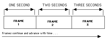
1. Frames

Behold the frame!, a self contained package of data. Remember, a sequence of bits makes up a frame. Frames organize data streams for efficiency, for ease of multiplexing, and to make sure bits don't get lost. In the diagram above we look at basis of time division multiplexing. As we've discussed, TDMA or time division multiple access, places several calls on a single frequency. It does so by separating the conversations in time. Its purpose is to expand a system's carrying capacity while still using the same numbers of frequencies. In the exaggerated example above, imagine that a single part of three digitized and compressed conversations are put into each frame as time goes on.
2. Slots
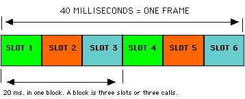
IS-54B, IS-136 frame with time slots

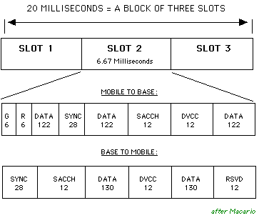
Welcome to slots. But not the kind you find in Las Vegas. Slots hold individual call information within the frame, remember? In this case we have one frame of information containing six slots. Two slots make up one voice circuit in TDMA. Like slots 1 and 4, 2 and 5, or 3 and 6. The data rate is 48.6 Kbits/s, less than a 56K modem, with each slot transmitting 324 bits in 6.67 ms. How is this rate determined? By the number of samples taken, when speech is first converted to digital. Remember Pulse Amplitude Modulation? If not, go back. Let's look at what's contained in just one slot of half a frame in digital cellular.Okay, here are the actual bits, arranged in their containers the slots. All numbers above refer to the amount of bits. Note that data fields and channels change depending on the direction or the path that occurs at the time, that is, a link to the mobile from the base station, or a call from the mobile to the base station. Here are the abbreviations:
IS-54B time slot structure and the Channels Within

G: Guard time. Keeps one time slot or data burst separate from the others. R: Ramp time. Lets the transmitter go from a quiet state to full power. DATA: The data bits of the actual conversation. DVCC: Digital verification color code. Data field that keeps the mobile on frequency. RSVD: Reserved. SACCH: Slow associated control channel. Where system control information goes. SYNC: Time synchronization signal. Full explanations on next page.
Still confused? Read this page over. And don't think you have to get it all straight right now. It will be less confusing as you read more, of my writing as well as others. Look up all of these terms in a good telecom dictionary and see what those writers state. Taken together, your reading will help make understanding cellular easier. E-mail me if you still have problems with this text. Perhaps I can re-write parts to make them less confusing.

