Object Oriented
Analysis and Design Using UML
A Whitepaper by Mark Collins-Cope
of Ratio Group.
Introduction
You're proficient in C++, Java or another OO language, you're
designing class hierarchies, using inheritance, and manipulating complex
pointer relationships to store the necessary links between your classes.
You've probably drawn blobs (representing classes in some way) on whiteboards,
with connecting lines to indicate the relationships between classes (inheritance
or other). Perhaps you're feeling the need for a more formal notation to
express your designs - using something that is language independent, and
that enables you to consider the important aspects of design leaving the
detail for later.
Alternatively, perhaps you're a Project Manager, looking to formalise
the OO design process a little to make sure you're getting the most from
your move to C++/Java or a similar language.
In this paper, I take a look at the UML (Unified Modelling Language)
notation for Object Oriented Analysis and Design - the emerging standard
designed by Booch, Rumbaugh and Jacobson, each of whom previously had their
own notations published independently.
The starting point is Object Modelling, a technique that enables you
to focus on class structure, inheritance, etc., whilst avoiding language
specifics such as pointer dereferencing.
Object Modelling In UML
Figure 1 - Subset of UML Object Modelling
Notation - A Summary
Object Modelling is the central technique in UML. It is a language independent
notation allowing the specification of classes, their data or attributes(private)
and methods (public), inheritance, and other more general relationships
between classes. The notation itself is fairly simple to grasp (see figure
1), however this hides the somewhat more subtle thought processes underlying
a good model.
The best way to understand the notation is to look at an example. The
following Object Model shows a simple Banking System, containing classes
for Head-Office, Branch, Accounts held at that Branch, and the Customers
who the Accounts belong to:
Figure 2 - A Simple Banking System Object
Model
Examining this Object Model in more detail, we can see the following
information about our class structure:
-
A Head-Office class (containing "bankName" and "address" fields, otherwise
known as attributes) "administers" an (unspecified) number of Branch
classes; whilst a Branch is "administered-by" exactly one Head-Office (the
little black arrows indicates the direction in which the name given to
a relationship should be read). On the diagram this relationship is represented
by the line from the Head-Office class to the Brach class which is labelled
"administers". The "1" at the Head-Office end of the line shows that exactly
one Head-Office is associated with each Branch (as you would expect). The
"*" at the Branch end of the line shows that a Head-Office "administers"
many Branches - again as you would expect.
-
Similarly, a Branch class (which contains "manager" and "address"
attributes) "holds" many Account classes; whilst each Account class "is-held-by"
exactly one Branch. We can also see that we have determined that
an Account class has a "CalcCharges" method (also known as operations or
member functions) defined. This method, when invoked, will look at the
detail stored within the Account object, and apply the appropriate (undoubtedly
extortionate) charges to the Account. The second method -"PrintStatement"
- will take the details of the Account and print them out.
-
The inheritance "triangle" (labelled "account-type") shows us that our
system knows about three types of Account: the basic account (in this case
a virtual class called Account), and two specialised accounts - the CurrentAccount
and SavingsAccount - which are derived from Account. The fact that the
"CalcCharges" is shown in both sub-classes indicates that its implementation
is re-defined for these classes (in C++ terms it is a virtual function).
This is indicative of the fact that charges on a "SavingsAccount" are calculated
in a completely different manner to charges on a "CurrentAccount".
-
Implicit in the decision to use inheritance and redefine methods in sub-classes
is the fact that the system, when implemented, will use the polymorphism
features of the target language (C++, Java ...) to enable all Accounts
to be treated in a single coherent fashion, regardless of the particular
charges mechanism involved. This is of course one of the reasons we use
an object-oriented development language in the first place.
-
Each Account "belongs-to" exactly one owner - the Customer class on the
diagram. Customers, on the other hand, may have many Accounts.
It's worth noting here that because an Account may "belong-to" a Customer,
both CurrentAccounts and SavingsAccounts may also belong to a Customer.
In other words, the "belongs-to" relationship between Accounts
and Customers is inherited by the CurrentAccount and SavingsAccount classes.
This fact simplifies the diagram considerably, removing the need for these
relationships to be noted explicitly. This simplification will also be
apparent in our final implementation of the system.
-
Finally, you can see that there are two relationships shown between
the Account and the Transaction classes. This is because, in our banking
system, each individual transaction (credit, debit, etc.) must have two
associated accounts - the Account the money is "debit(ed)-from", and the
Account the money is "credit(ed)-to". This enables the bank to record exactly
where each transaction has come from, and gone to, so to speak.
These last point brings out an interesting feature of what is being shown
on an Object Model: clearly it wouldn't make sense for each Transaction
to be "debit(ed)-from" and "credit(ed)-to" the same Account - no money
would be transferred! Obviously, although the lines (relationships) are
shown to the same Account class, they do not (necessarily) represent links
to the same Account object at run-time.
A relationship shown on an Object Model indicates that some kind of
run-time link will exist between two instances of the classes shown on
the Object Model. Thus the Branch to Accounts relationship should be read
as follows:
An instance of the class Branch will be linked to (zero to) many
instances of the class Account, whilst an instance of the class Account
will be linked to (one and only) one instance of the class Branch.
This can be shown more clearly by the following instance diagram (instance
diagrams are used to assist in understanding and clarifying Object Models
- they also give quite a hint as to how relationships can be implemented
in C++!): 
Figure 3 - Instance Diagram Showing Branch
and Account objects
By now, you may be beginning to see how Object Models can assist the
analysis/design process. They assist in the clarification of the relationships
that should be (somehow) represented in a software system. The important
point to note hear is that we are first working out what relationships
we need to represent in our system ("belongs-to", etc.), without worrying
too much about exactly how they should be stored. Put another way, Object
Modelling allows us to focus on exactly what problem we are trying to solve,
before we look at the best way of implementing our model in a particular
programming language.
Implementing Object Models
OK, that's fine, you may say, but how do Object Models relate to C++
or Java, exactly? Lets take a look at a sub-set of our previous example
: 
Figure 4 - Subset of Banking Model
Our Object Model shows us that we need four classes: Transaction; Account;
Current Account and Savings Account, and that our implementation must enable
us to represent the fact that any particular Account has two sets of Transactions
associated with it - which will be needed to implement the PrintStatement
method. The Account, CurrentAccount and SavingsAccount classes are easily
mapped to the C++ (or Java) inheritance mechanisms:
class Account {
/* ... data ... */
public:
virtual void CalcCharges();
void PrintStatement();
};
class SavingsAccount : public Account {
/* any additional data */
public:
virtual void CalcCharges();
/* re-definition */
/* use the base class PrintStatement
method */
};
class SavingsAccount : public Account {
/* any additional data */
public:
virtual void CalcCharges();
/* another re-definition */
/* use the base class PrintStatement
method */
};
Figure 5 - Mapping Object Model Inheritance
To C++ Inheritance
The Transaction class may be implemented as follows:
class Transaction {
long value;
/* stored in pence */
date_t date; /* date
of transaction */
public:
/* Access and Update
functions */
Date(date_t); /* set
*/
date_t Date(); /* get*/
Value(long); /*
set */
long Value(); /* get
*/
};
Figure 6 - Transaction Class In C++
This leaves us with the "debit-from" and "credit-to" relationships to
be implemented. Here we have a number of choices: linked-lists; collection-classes;
(dynamically bounded) arrays of pointers; etc. could all be used to represent
these relationships.
class TransactionList {
TransactionList * next; /*
ptr to next element */
Transaction * data;
/* store the transaction here */
public:
void Data (Transaction *);
/* set */
Transaction * Data();
/* get */
void NextItem(TransactionList
*); /* set next ptr */
TransactionList * NextItem();
/* get next ptr */
};
Figure 7 - Simple Transaction List Handler
Class
For brevity, a linked-list class with a somewhat limited interface is
used in this example - although this may not the best choice.
Amending our Account class definition to use this class gives us the
following new definition:
class Account {
TransactionList * debitedFrom;
/* debited from Tx list*/
TransactionList * creditedTo;
/* credited to Tx list */
public:
virtual void CalcCharges();
void PrintStatement();
/* some new methods to manipulate
the Transaction list */
DebitTx (Transaction *); /* Add a debit Tx */
CreditTx (Transaction *); /* Add a credit Tx */
Transaction* NextDebitTx(); /* Iterator:get
debit Tx */
Transaction* NextCreditTx(); /* Iterator:get cred Tx
*/
};
/* sample method implementation */
Account::DebitTx(Transaction * theTx) {
/* add a
new list contained at the beginning of the list */
TransactionList * tmpTxLp = debitedFrom;
debitedFrom = new TransactionList;
debitedFrom->NextItem(tmpTxLp);
/* new put the transaction data into the list */
debitedFrom->Data(theTx);
};
Figure 8 - Account Class amended to use
Transaction List
Although this is a somewhat simplistic implementation - it demonstrates
the point that the model shown in figure 4 is easily translated into C++.
Of course, better implementations of the "debit-from" relationship are
possible, but the fact that the Account class interface completely hides
the underlying implementation of this relationship means that we can improve
on our first cut implementation at a later date with little impact on our
overall system code. In other words, use of the Account class interface
has limited the impact of the relationship implementation method: something
we strive to achieve when writing OO based applications.
A couple of other points are worthy of note at this stage:
-
The linked list class contains pointers (references in Java) to Transaction
objects. This is implicit in our Object Model, and is what the system's
users would expect to see. To see why, consider the case when a new Transaction
value is entered in error. The Transaction is linked to two accounts ("debit-from"
and "credit-to"). If the Transaction object is shared, only one object
need be modified to rectify the situation. Using two objects would either
mean that either the system has to update two objects (equals more coding
work), or that the user has to update two Transactions (equals greater
potential for mistakes).
-
Although our Object Model "debit-from" relationship uses a linked list,
there are many alternatives to this choice - including the use of a relational
database to underpin the system. The point is, however, no matter what
mechanism is used, we are actually trying to implement a "many-to-one"
relationship between an Account and a Transaction. It is this relationship
that exists in the banking problem domain - not a relationship involving
linked lists or collection classes. Object Modelling enables us to spot
the relationship required by the problem domain, and then choose the best
way of implementing it.
-
So far, we have only implemented the "debit-from" relationship in one direction-
from the Account class to the Transaction class. Our model does not (yet)
specify in which direction the relationship will be traversed. If we need
to traverse the relationship in both directions - getting from the Transaction
to the related Account - our implementation will prove insufficient, and
some form of double pointer schema may be needed. Much work would have
been saved if we had known this fact before we had started writing the
code.
-
Although our Object Model provided a starting point for our implementation,
it was not complete, for example new methods have been added to the Account
class.
-
Other factors may also influence our choice of implementation: do we need
a direct form of access - for example using a Transaction number to go
directly from the Account to the relevant Transaction? If we do, then a
linked-list will prove an inefficient choice of implementation. Again,
it would be very useful to know this type of information before we start
trying to implement the relationship.
From these points we can see that we need to consider the wider
requirements of our system before we can come up with the right implementation
of our "debit-from" relationship (not to mention the many other classes
and relationships that might be required). We can't produce a good design
for a system unless we consider all the required functionality - in detail.
Use Cases provide the mechanism for doing this.
Use Cases In UML
Use Cases are used to document system requirements. They provide a
useful technique which, in conjunction with Object Modelling, help us to
clarify exactly what the system is supposed to do. Let's take a look at
the requirements for our banking system
: 
Figure 9 - Use Cases for Banking System
This Use Case diagram shows us the following:
-
The required business functions - that is, the type of operation you'd
expect to find on the menu of the application once it had been developed.
In this case we have identified the following functions:
-
Bank managers need to periodically print out a report detailing all the
customers who are overdrawn; these appear on the branch printer
-
Customers may use the system for balance enquiries
-
Data processing staff use the system to do basic data entry (transactions
on accounts)
-
Clerks may periodically request statements on behalf of Customers;
-
There are four distinct types of user of the system: Bank Managers; Clerks;
Data Processing Assistants; and Customers. Each type of user typically
has their own particular set of requirements for a system: hence identify
user types assists in identifying all the required system functions.
The Use Case diagramming technique allows us to make a first cut at defining
the system requirements, and will help us in presenting these requirements
back to the users of the system. It also partitions the system into single
atomic business functions, which may be used as a basis for costing the
system, or for planning a phased system delivery. In this case each successive
phase would deliver further batches of Use Cases.
Further information is still required, however, to tie down the detail
of what each businese function does. Use Case Detail provides this information
(explanatory notes are shown in bold):
| Use Case Detail: Overdrawn
Report
Used By:
Bank Manager
Inputs:
Details what information flows from the user to the system for this
particular Use Case.
theBranchSortCode - The Sort Code of the branch for which the report
is required.
theOverdraftPeriod - how long an Account has been overdrawn before
it is forms part of the report.
Outputs:
Details what information flows from the system to the external environment,
in this case the printer!
overdraftReport (to branchPrinter) - structured as follows: customer
name; current overdraft; period overdrawn (days);
Printed for all accounts that have been overdrawn for a
period greater than theOverdraftPeriod, and which have not already been
reported (on another report) in the last 30 days.
Pre-Conditions:
What validity checks or constraints apply on the inputs (or the
internal system as a whole, in some cases).
theBranchSortCode - must be a branch sort code held within the system.
theOverdraftPeriod - must be a number between 0 and 100 days.
Post-Condition:
What changes does the Use Case make to the internal system state.
Updates the reportedOnDate field of overdrawn accounts.
|
As work progresses on the Use Cases, the requirements of the system
become clearer enabling the Object Model to be updated in parallel, helping
us make sure our model (and the subsequent implementation in the chosen
language) contains all the necessary classes and class inter-links.
Whilst we're nearer to resolving some of the issues identified at the
end of the discussion of implementing Object Models, a number are still
outstanding: we still can't be sure in what direction the relationships
must be implemented, whether we have identified all the methods; or what
implementation of the links will best suit the use to which they'll be
put. To sort out the remaining issues we'll need to look in more detail
exactly how each Use Case will be implemented, using Sequence Diagrams.
Sequence Diagrams
Sequence diagrams, performed on a per Use Case basis, examine the flow
of method call calls within a system. 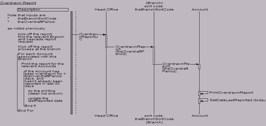
Figure 10 - Sequence Diagram for Overdrawn
Report
Performing a complete analysis requires that each individual Use Case
must be examined, although in practise only selected Use Cases may be examined.
The Sequence Diagram in figure 10 shows the Overdrawn Report Use Case defined
earlier.
The Overdrawn Report Use Case is thus implemented as follows:
-
The Head-Office object (there is only one of them) has methods which correspond
to each Use Case - in this case an OverdrawnReport method (this is a convenience
for brevity, normally there would be a single "InitialObject" which the
system would know about, and which would provide the entry point into the
run-time model for all code).
-
The Head-Office OverdrawnReport method locates the relevant Branch (as
determined by the Use Case input: theBranchUseCase) and cascades the request
to the Branch by calling its OverdrawnReport method.
-
The Branch object in turn passes the request on down to each Account it
holds (using the Account's OverdrawnReport method)!
-
Each Account then:
-
checks if it has been overdrawn for greater than the period specified by
theOverdraftPeriod, which is passed as an argument to the Account.OverdrawnReport
method (the detail of this is not shown - but involves summing up all the
Transactions it holds, and checking the date on which it last became overdrawn).
-
if appropriate it then calls one of its own methods to print the report
(detail not shown), and resets its lastReportDate attribute, again using
its own method.
-
The method calls unwind until the Use Case is complete.
Figure 11 - Updated Banking System Object
Model
Reviewing the Object Model (see figure 11), we can see a number of additions
as a result of completing this Sequence Diagram:
-
OverdrawnReport methods have been added to the Branch and Account classes.
-
A lastReportedDate attribute and associated methods have been added to
the Account class, along with a printOverdrawnReport method.
-
The "administers" relationship between Head-Office and Branch has been
qualified to indicate that "direct access" via the Branch's "sort-code"
is required across the link (thus assisting in link design) - note the
consequent change in the multiplicity of the relationship from many-to-one
to one-to-one.
-
We have added directionality to many of the links (e.g. see the arrow-head
on the Branch to Account link).
Of course, we've only looked at one Use Case, so its likely the model will
change further as more sequence diagrams are developed.
The Overall Process
From the above discussion we can see that Use Cases and Sequence Diagrams
both add to integrity and completeness of our Object Model, and that a
good Object Model provides a firm foundation for a good design, and hence
a good implementation of the system.
Figure 12 - The Overall Process
This approach separates the Problem and Technical Domain aspects of
the project:
-
Problem Domain Analysis is concerned with capturing requirements and producing
a first cut Object Model. Typically the Object Model will be incomplete,
having only a subset of the class attributes and methods defined.
-
Problem Domain Design is concerned with finalising the detail of the problem
domain parts of the Object Model, and results in an Object Model with a
complete set of Problem Domain specific classes, attributes and methods.
-
User Interface Design is the first step that focuses on the Technical Domain
aspects of the problem, and involves taking the Use Cases as defined earlier,
and designing a Graphical User Interface appropriate to the Technical Architecture
chosen for the project (MS Windows, X/Motif, etc.). Typically you would
expect to find one controlling dialog box (which may use other subsidiary
dialogs) for each Use Case in the system. Some prototyping may be appropriate
at this point in the project. For small projects, prototyping and UI design
may be undertaken in parallel with Use Case development.
-
Technical Domain, High Level Design focuses on adding classes to meet the
technical needs of the project, and is driven by the technical architecture
of the project. Classes may be GUI related, DBMS (object or relational)
related, distribution related (CORBA, DCOM, etc.), external systems related,
or may provide an interface to internal system components such as printers.
Previous Sequence Diagrams may be updated to confirm the validity of the
technical design - in particular you would expect to see GUI classes appearing
between the System Boundary and the Problem Domain classes.
-
Finally, Detailed Technical Design, looks at link implementations, detailed
data typing of attributes, full specification of all methods (including
parameters), etc. The end result is a complete design of the full system.
The separation between Problem Domain and the Technical Domain aspects
of the system is useful in large projects, allowing the focus of those
working on the project to be clearly divided, as summarised in figure 13:
Figure 13 - Seperation Of Problem and Technical
Domain Components of a System
For smaller projects (one or two persons for a couple of months) the
two domains may be merged, if desired.
As mentioned previously, Use Cases may be used in phasing a project;
the process shown earlier does not prohibit this. A project with 50 Use
Cases could be structured in three phases as shown in figure 14:
 Figure
14 - Evolutionary Phasing Of OO Project
Figure
14 - Evolutionary Phasing Of OO Project
The object-based structure of the application lends itself well to this
approach.
Summary
This paper has taken a look at the Use Case, Object Modelling, and
Sequence Diagramming notations of UML, how Object Modelling maps to OO
programming languages, and shown how these notations hang together to complement
each other. A number of other UML notations are not covered in this article,
however further information can be found on www.ratio.co.uk.
I hope you can see that OOA/D offers a number of potential benefits
in an OO based development environment. These include:
-
better modelling of the problem domain (equals happier users)
-
better overall software design with a strong focus on class structure
-
more flexible and maintainable systems through better class partitioning
-
good documentation (the notations) - and a single central overall design
notation (the Object Model)
-
a flexible approach to project phasing
-
assistance in tie-ing down requirements, and
-
less work (in the long run)
Mark Collins-Cope is Technical Director at Ratio Group Ltd., a consultancy
and training company specialising in OO related methods, languages and
technologies. For further information on OOA/D using UML, Java, C++, Design
Patterns or related topics please contact us
Copyright
This material remains the copyright of Ratio Group Ltd. Licence
is granted for the use of this material for personal development purposes
only.