 Caption:
Context:
Problem Definition
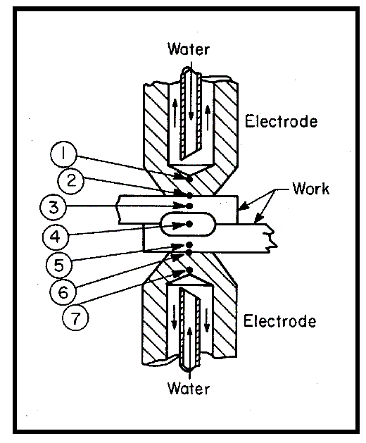
In the electric resistance spot welding
process shown in Fig. 1, electrodes 1
and 7 press against workpieces 3 and
5. A current is then passed through these
components. Because of the electrical
contact resistance, heat will be generated
at electrode/workpiece interfaces 2 and
6 and faying surface 4. The heat at the
faying face melts the workpieces to form
a nugget, 4. To prevent melting at the
electrode/workpiece interface, water is
circulated in the cooling chamber of the
electrodes -- Fig. 1. For a reduction of the
problem size in this investigation, only
one electrode was considered. This approach
requires knowledge of the power
input (determined experimentally) at the
electrode/workpiece interface.
Both the ambient air and initial water
temperatures were assumed to be 20°C
(68°F). If the water does not boil, the
physical properties can be assumed to be
temperature independent. A complete
conjugate heat transfer solution can be
performed in two separate steps: 1) a
steady-state mechanical solution assuming
an imposed coolant flow rate and
pressure at the inlet of the water pipe, and
2) a transient thermal solution. This approach
uncoupling the mechanical
and the thermal solutions, using the assumption
of temperature-independent
material properties substantially reduces
the computational time. The welding
cycle, i.e., the time to make one spot
weld that encompasses several cycles
of alternating current, was taken as the
duration of the transient solution time.
Abstract:
The accurate thermal simulation
of a spot welding electrode cap
could permit critical design parameters
to be identified for improved electrode
life. In this study, a parametric model has
been developed to predict the transient
thermal behavior of a typical spot welding
electrode cap. The model employs
the technique of conjugate heat transfer
analysis to avoid the problem of estimating
a value for the heat transfer coefficient
that arises with conventional heat
transfer analysis.
Using experimental values for the
input power, the predicted maximum tip
surface temperature was 905 K. Traces of
aluminum melting at the cap/aluminum
interface are often observed in practice in
the spot welding of aluminum. Since aluminum
alloys have melting points of
∼900 K, the simulation closely predicts
the tip surface temperature.
The analysis indicated that convective
and radiant heat losses were not important.
A simple linear relationship between
the maximum temperature and the
input power was found. For very short
heating times, no significant changes
were found in the maximum temperature
reached for a decrease of the coolant
flow rate from 3.79 L/min (1.00 gal/min)
to 2.24 L/min (0.75 gal/min), or for a decrease
of the cap depth -- the distance
between the tip working surface and the
cooling surface -- from 9.00-6.35 mm.
The overall behavior is typical to that of
components with a slow thermal response,
but a fast heating rate.
Source:
1. Murphy, A. J., Yeung, K. S., & Thornton, P. H.
(1999). Transient Thermal Analysis of Spot Welding
Electrodes. Welding Journal (Supplement), January,
1s-6s.